


MPPT Solar Charge Controller 60A-120A 12V 24V 48V High Efficiency Power Management For Solar Systems
- Product Name:Tracer Dream F Series/TD F Series
- Product Type: MPPT solar controller
-
Rated charge current: 60A 80A 100A 120A
- System Voltage: 12V/24V/48V auto
- Max. PV open circuit voltage:150V/200V/250V
- Communication:External WiFi/Bluetooth(optional)
- Battery: Support lithium battery and multiple battery type
- Start from PV : Support
- Cooling Mode:Fan Cooling
-
Terminals: Large Terminals
- 16 Safety Protections:High-Temperature Charging Power Derating Protection、Real-time Energy Statistics Function、Power Limited Protection......
- Accessories: Free App Service
Use LDSOLAR Controller Build Off-grid Solar System
Tracer Dream F Series
60A / 80A / 100A / 120V
12V-24V-48V / Max. 150V/200V/250V Solar Input
Tracer Dream F Series controller is based on Multi phase synchronous rectification technology and advanced MPPT controlalgorithm, adopt co-negative design, with LcD displaving running status, The MPpT control algorithm can minimize themaximum power point loss rate and loss time, quickly track the maximum power point of the PV array and obtain the maximumenergy from solar modules under any conditions; and can increase the ratio of energy utilization in the solar system by 20%-30% compared with a PWM charging method.
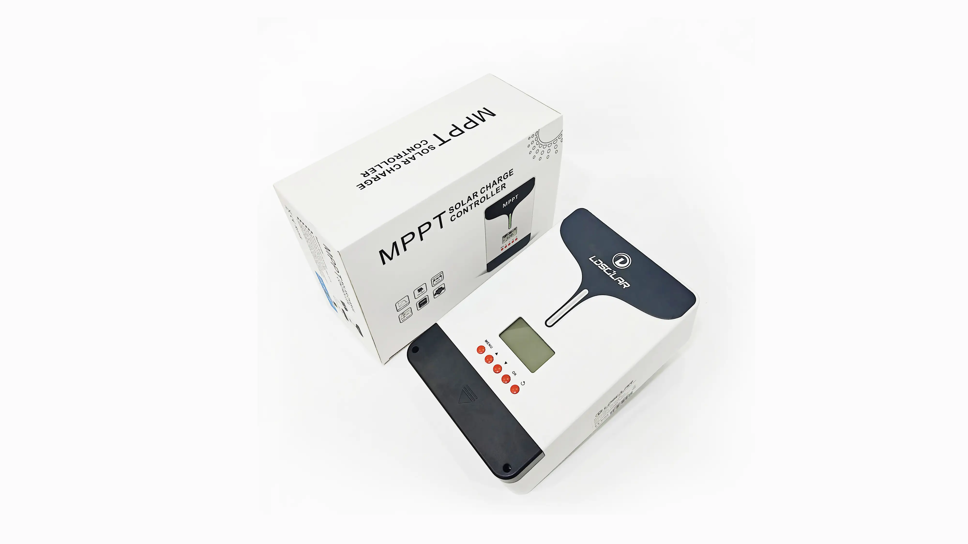
Product Details
The controller adopts simple design, with a
harmonious proportion and beautiful appearance.
Highlights
The Tracer Dream Series Solar Charge Controller combines advanced digital technology with robust construction to deliver superior performance. Key features include:
Parameter
Detailed explanation of specific parameters
| Item | TD4615F | TD4815F | TD41015F | TD4820F | TD41020F | TD41220F | TD4825F | TD41025F |
| System nominal voltage | 12/24/48VDC Auto ① | |||||||
| Rated charge current | 60A | 80A | 100A | 80A | 100A | 120A | 80A | 100A |
| Rated discharge current | 30A | / | / | / | / | / | / | / |
| Battery voltage range | 8~68V | |||||||
| Max. PV open circuit voltage | ② 150V ③138V | ② 200V ③ 180V | ② 225V ③ 250V | |||||
| MPP voltage range | (Battery voltage +2V)~ 108V | (Battery voltage +2V)~ 144V | (Battery voltage +2V)~ 190V | |||||
| Max. PV input power | 800W/12V 1600W/24V 3200W/48V | 1000W/12V 2100W/24V 4200W/48V | 1300W/12V 2600W/24V 5200W/48V | 1000W/12V 2100W/24V 4200W/48V | 1300W/12V 2600W/24V 5200W/48V | 1500W/12V 3000W/24V 6000W/48V | 1000W/12V 2100W/24V 4200W/48V | 1300W/12V 2600W/24V 5200W/48V |
| Self-consumption | ≤50mA(12V)/37mA(24V)/27mA(48V) | |||||||
| LVD | 11.0V ADJ 9V….12V;×2/24V;×4/48V | |||||||
| LVR | 12.6V ADJ 11V….13.5V;×2/24V;×4/48V | |||||||
| Float voltage | 13.8V ADJ 13V….15V;×2/24V;;×4/48V | |||||||
| Boost voltage |
14.4V ; ×2/24;×4/48V Battery Voltage less than 12.6V Start Boost changing for 2hours(Li-battery not) |
|||||||
| MPPT tracking efficiency | ≥99.5% | |||||||
| Max. Conversion efficiency | 98% | |||||||
| Grounding | Common negative | |||||||
| Battery Type | Sealed(Default)/Gel/Flooded/LiFePO4/ Li(NiCoMn)O2/ User | |||||||
| Temperature compensate Coefficient ④ | -4mv/℃/2V | |||||||
| Communication method | RS485(5VDC/200mA) | |||||||
| LCD backlight time | Default: 15S | |||||||
| Working environment temperature◆ | -20℃~+50℃(100% input and output) | |||||||
| Storage temperature range | -20℃~+70℃ | |||||||
| Relative humidity | ≤95%, N.C. | |||||||
| Enclosure | IP32 | |||||||
①When a lithium battery is used, the system voltage can’t be identified automatically.
②At minimum operating environment temperature
③At 25℃ environment temperature
④When a lithium battery is used, the temperature compensate coefficient will be 0.
◆The controller can work under full load in the working environment temperature, When the internal temperature is more than 80℃, the reducing power charging mode is turned on.
Installation Diagram
Please be sure to follow the wiring instructions as incorrect wiring can cause damage to the controller.